Finned Tubular Heaters
GLOW.jpg)

 |
 |
 |
PRODUCT DESCRIPTION
Finned
Tubular Heaters are normally used in forced circulation heating of low
temperature air, other atmospheres and gases. Typical applications include
forced convection heating of air, process atmospheres, and oven atmospheres in
duct environments. Steel finned tubular heaters are standard with surface
temperatures limited to about 425�C (797�F) compared to 815�C (1500�F) for an
alloy sheathed non-finned heater.
Some applications require
stainless steel materials for corrosion resistance. The most efficient finned
heaters are made with steel sheath and steel fins. Steel is normally used for
air heating, stainless steel for atmospheres which are humid or corrosive and
monel for salt-laden humid atmospheres. Keep in mind that stainless heaters
with stainless fins are very inefficient since the heat transfer rate of
stainless is less than one quarter that for steel. Finned Tubular Heaters offer distinct advantages over open coil heaters: (a) they are safer to operate
in that the risk of fire or electrical shock are minimized; (b) they have a
much longer service life; and (c) they are more rugged requiring less
maintenance than open coil heaters.
We offer a standard
carbon steel construction and a high temperature/ corrosion resistant stainless
steel construction. As with regular tubular elements, they can be bent to a
number of shapes and are available with fittings and mounting brackets as
required. Typical Applications Wattage Required to Heat Air
Flows: http://www.nphheaters.com/quote/industrial_process_heaters/wattage_required.pdf To Order Finned Tubular Heaters
Please Specify:
Bend Formations Below: NPH Tubular Heater Bend Formations.pdf nominal dimensions nominal dimensions nominal dimensions nominal dimensions nominal dimensions nominal dimensions nominal dimensions nominal dimensions nominal dimensions nominal dimensions nominal dimensions nominal dimensions
![]() Finned Tubular Heater Specifications.pdf
Finned Tubular Heater Specifications.pdf
![]() Tubular Heater Bend Formations.pdf
Tubular Heater Bend Formations.pdf
![]() Electric Tubular Heaters Wiring Diagrams
Electric Tubular Heaters Wiring Diagrams
![]() Radiant Heating
Radiant Heating ![]() Convection - Air and Gas
Convection - Air and Gas ![]() Recirculation Ovens
Recirculation Ovens![]() Shrink Tunnels
Shrink Tunnels ![]() Dryers
Dryers ![]() Heat Treating
Heat Treating![]() Annealing
Annealing
![]() Element diameter andsheath material
Element diameter andsheath material ![]() Fin Material
Fin Material ![]() Terminal Type
Terminal Type![]() Total Sheath Length
Total Sheath Length ![]() Cold Section at Each End
Cold Section at Each End![]() Voltage and Wattage
Voltage and Wattage ![]() Bending Configuration Drawings-see link below:
Bending Configuration Drawings-see link below: ![]() Quantity
Quantity![]() Mounting Characteristics and accessories (if required)
Mounting Characteristics and accessories (if required)![]() Special Moisture Resistant Seal (if required)
Special Moisture Resistant Seal (if required) ![]() Bending Formation Drawings – See link below:
Bending Formation Drawings – See link below:
How To Order Finned Heaters
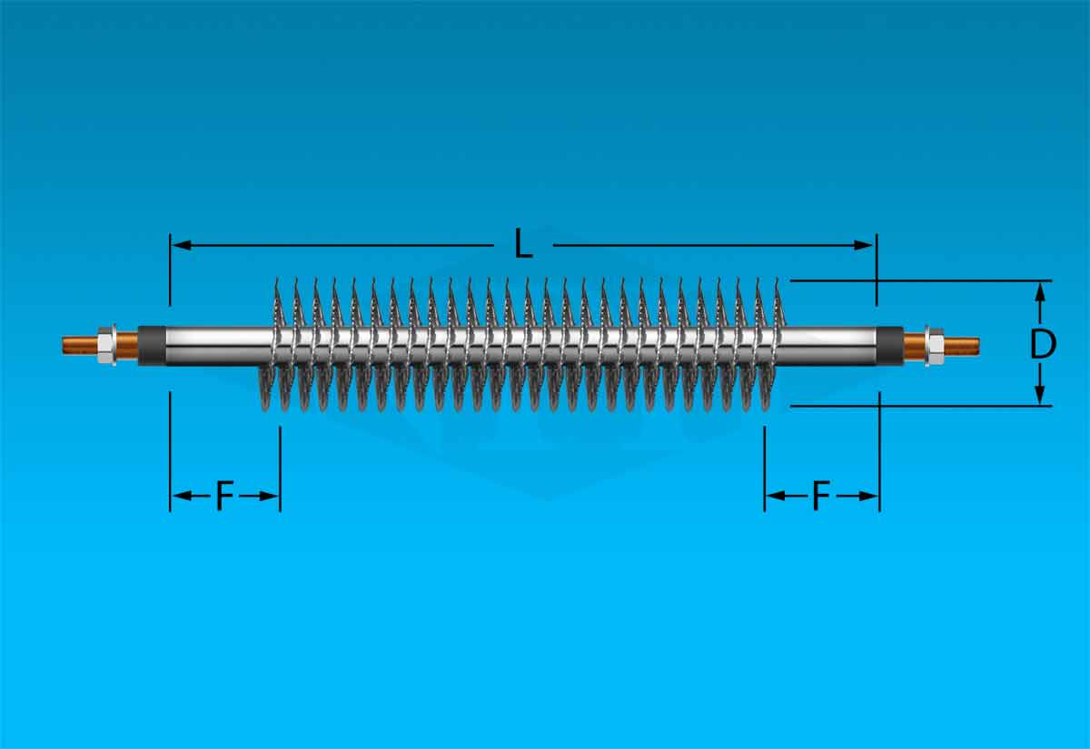
Finned Tubular Element:1
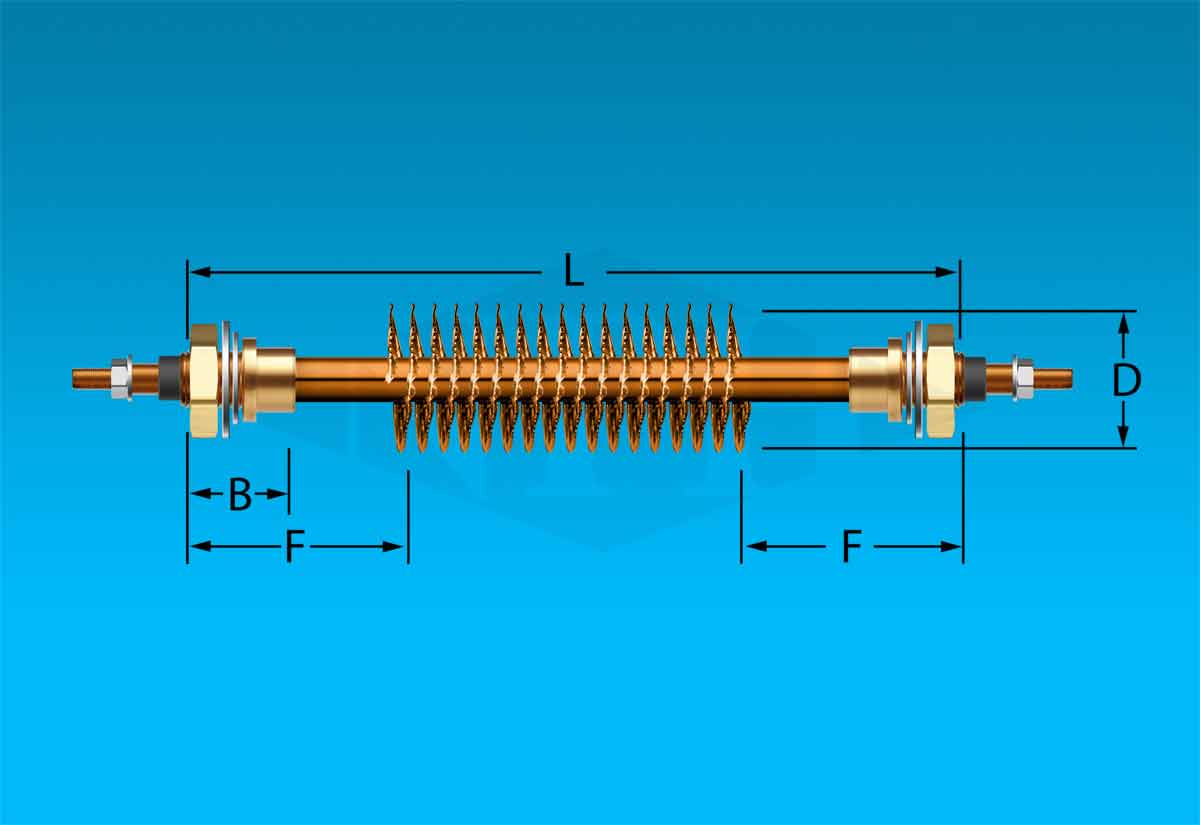
Figure 1 - 0.315"
kw
L
part no.
1
2
3
4
5
6
19
34
49
64
79
94
ASB-301S
ASB-302S
ASB-303S
ASB-304S
ASB-305S
ASB-306S
F = 5/8"
Figure 1 - 0.430"
kw
L
part no.
2
3
4
5
6
7
8
27
39
52
64
77
89
102
ASB-402S
ASB-403S
ASB-404S
ASB-405S
ASB-406S
ASB-407S
ASB-408S
F = 5/8"
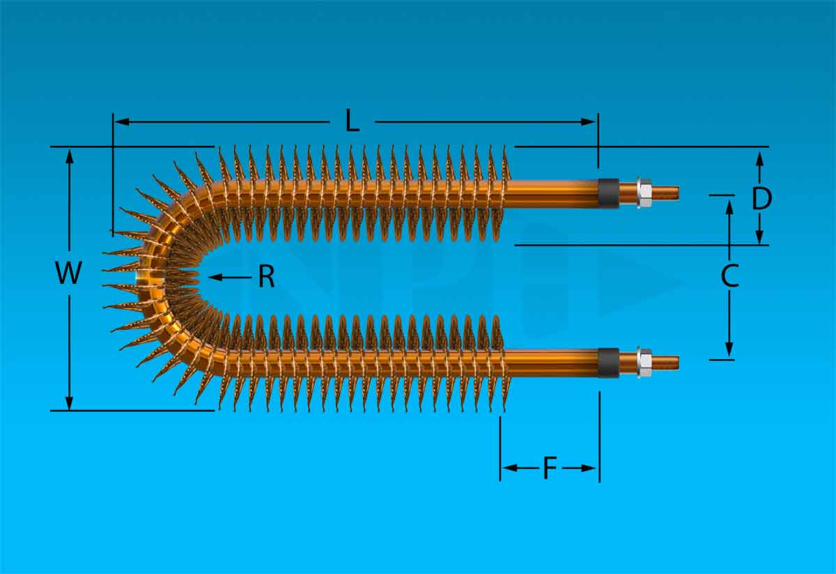
Figure 2 - 0.315"
kw
L
part no.
1
2
3
4
5
19
16
24
31
39
ASB-301U-A
ASB-302U-A
ASB-303U-A
ASB-304U-A
ASB-305U-A
C = 2 1/2"
F=5/8"
R = 1 9/16"
W = 3 3/8"
Figure 2 - 0.430"
kw
L
part no.
2
3
4
5
6
7
8
13
20
26
32
38
44
51
ASB-402U-A
ASB-403U-A
ASB-404U-A
ASB-405U-A
ASB-406U-A
ASB-407U-A
ASB-408U-A
C = 3"
F=5/8"
R = 2"
W=4"
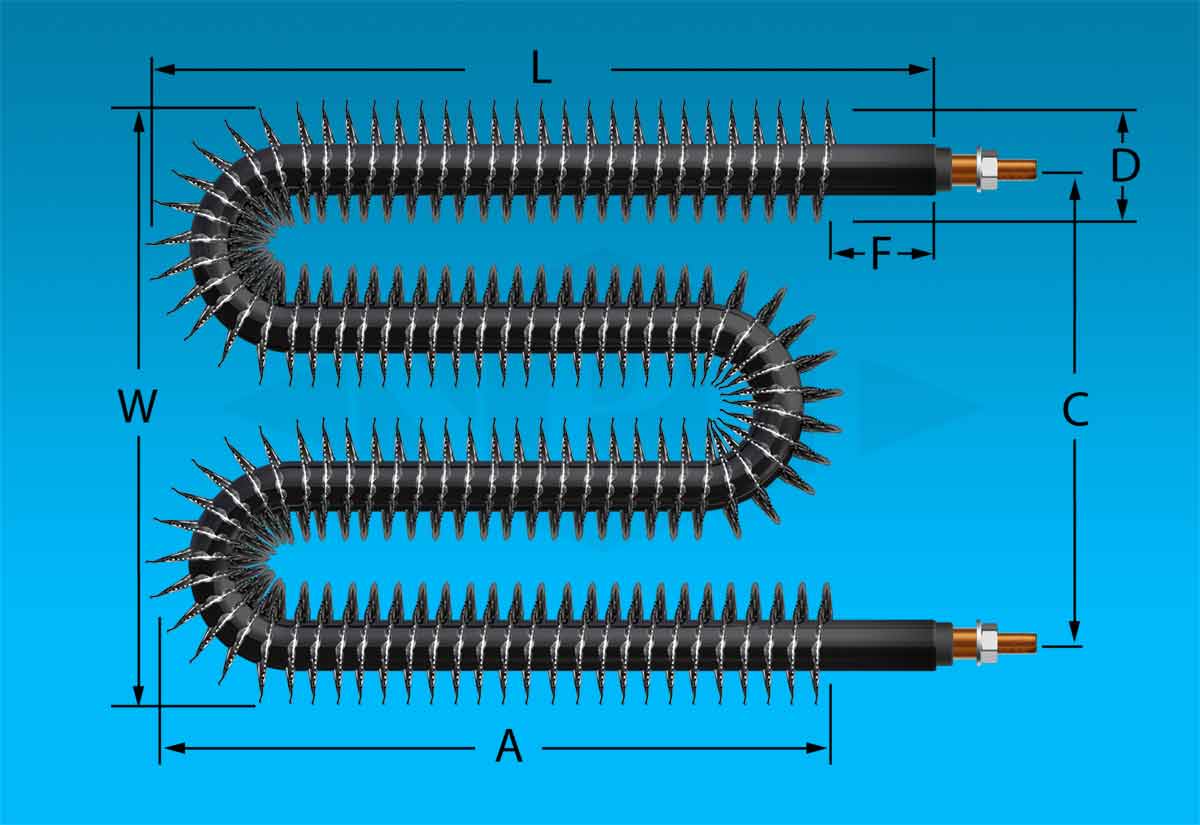
Finned Tubular Element:3
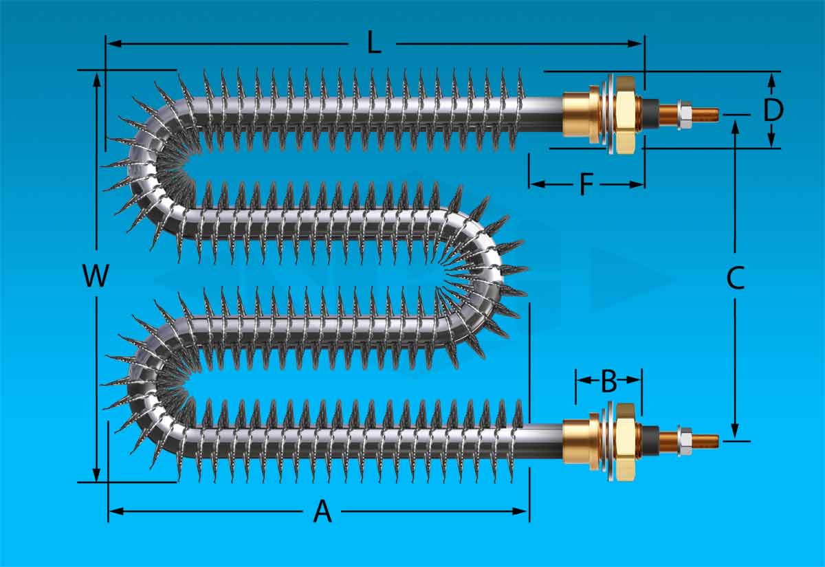
Figure 3 - 0.315"
kw
L
part no.
1
2
3
4
5
6
10
13
17
20
ASB-301W
ASB-302W
ASB-303W
ASB-304W
ASB-305W
A=L-F
C=4½"
F=5/8"
W=5½"
Figure 3 - 0.430"
kw
L
part no.
2
3
4
5
6
7
8
7
10
14
17
20
23
26
ASB-402W
ASB-403W
ASB-404W
ASB-405W
ASB-406W
ASB-407W
ASB-408W
A=L-F
C=6"
F=5/8"
W=7 1/8"
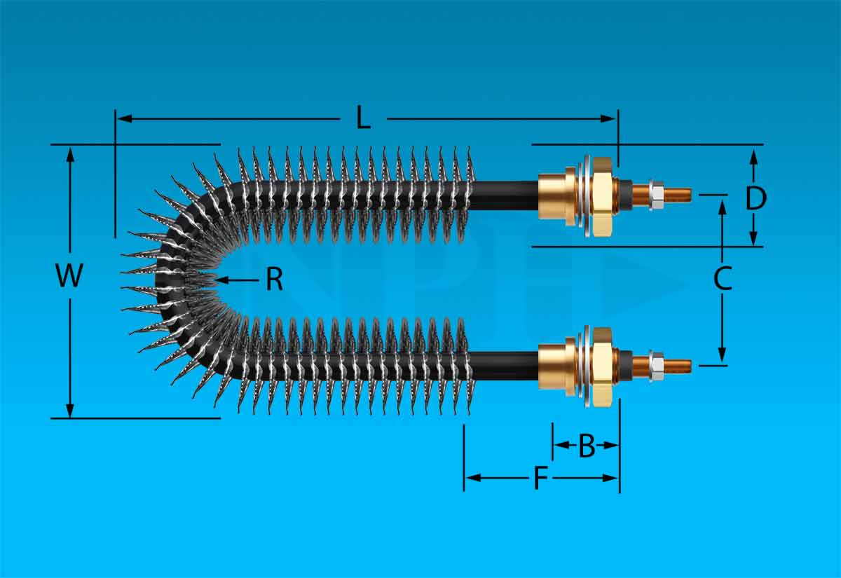
Figure 4 - 0.315"
kw
L
part no.
1
2
3
4
5
6
20.5
35.5
50.5
65.5
80.5
95.5
ASB-301SF
ASB-302SF
ASB-303SF
ASB-304SF
ASB-305SF
ASB-306SF
F=2 1/8"
Figure 4 - 0.430"
kw
L
part no.
2
3
4
5
6
7
8
28.5
40.5
53.5
65.5
78.5
90.5
103.5
ASB-402SF
ASB-403SF
ASB-404SF
ASB-405SF
ASB-406SF
ASB-407SF
ASB-408SF
F=2 1/8"
Figure 5 - 0.315"
kw
L
part no.
1
2
3
4
5
6
10.5
17.5
25.5
32.5
40.5
47.5
ASB-301UF
ASB-302UF
ASB-303UF
ASB-304UF
ASB-305UF
ASB-306UF
C=1½"
F=2 1/8"
W=2½"
Figure 5 - 0.430"
kw
L
part no.
2
3
4
5
6
7
8
14.5
21.56
27.5
33.5
39.5
45.5
52.5
ASB-402UF
ASB-403UF
ASB-404UF
ASB-405UF
ASB-406UF
ASB-407UF
ASB-408UF
C=2"
F=2 1/8"
W=3 1/8"
Figure 6 - 0.315"
kw
L
part no.
1
2
3
4
5
6
7.5
11.5
14.5
18.5
21.5
25.5
ASB-301WF
ASB-302WF
ASB-303WF
ASB-304WF
ASB-305WF
ASB-306WF
A=L-F
C=4½"
F=2 1/8"
W=5"
Figure 6 - 0.430"
kw
L
part no.
2
3
4
5
6
7
8
8.5
11.5
15.5
18.5
21.5
24.5
27.5
ASB-402WF
ASB-403WF
ASB-404WF
ASB-405WF
ASB-406WF
ASB-407WF
ASB-408WF
A=L-F
C=6"
F=2 1/8"
W=7 1/8"


 We Ship Our Industrial Process Heaters To OEM’s & Industry World Wide.
 Email:
  Tel:
Tel: 
